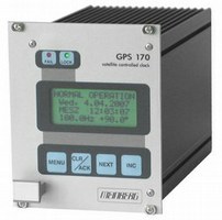
GPS 170
GPS satellite receiver.
Key features
- Standard frequency outputs
- Pulses per second and per minute
- 2 time trigger inputs
- 2 RS232 interfaces
- Alarm output
- DDS frequency synthesizer
- DCF77-simulation
- Antenna connected with up to 250m of standard coaxial cable RG58
- DC-insulated antenna circuit
- Flash-EPROM with bootstrap loader
- Optional up to 4 serial ports
- 3 programmable switching outputs
- timecode generator (IRIG-B, AFNOR)
Detailed description
The frequency locking of the master oscillator to the GPS system enables the module GPS167 to generate fixed and programmable standard frequencies with high accuracy and stability. Various oscillator options allow the cost efficient implementation of different requirements concerning the accurracy of the outputs.
The pulse generator of GPS167 generates pulses per second and per minute. As an option three programmable outputs are available. The pulses are synchronised to UTC second.
Up to four serial interfaces are available for sending time strings. These ASCII telegrams include information regarding time, date and status of the GPS receiver.
The module provides two inputs for measurement of asynchronous time events. These capture events are shown on the LC display and can be read via a serial interface.
The front panel integrates a LC display that shows information regarding the GPS receiver in different menus. In combination with four push buttons it is also used to setup all configurable parameters.
Technical data
| Type of receiver: | 6 channel C/A-code receiver |
|---|---|
| Type of antenna: | Remote powered GPS antenna/converter unit, up to 250m antenna cable RG58 |
| Display: | LC-display, 4 x 16 characters, content of display selectable by menu UTC time or local |
| Cable type: | Coaxial cable RG58 indoor or outdoor usage (BNC-, N-Norm-connector) |
| Status info: | Fail-LED shows that the internal timing has not been synchronized or that a system error occured Lock-LED shows that the calculation of the position has been achieved after reset |
| Synchronisation time: | Max. 1 minute in normal operation mode, approx. 12 minutes after a cold start (discharged buffer battery) |
| Frequency outputs: | 10 MHz, 1 MHz, 100 kHz (TTL level) Synthesizer 1/8 Hz up to 10 MHz (TTL level, sine wave 1.5Veff, open drain) Accuracy: ±1·10E-9 (timebase OCXO LQ), GPS-synchronous for more than 20 minutes Different oscillators available, look at oscillator options |
| Pulse outputs: | Pulse per second and pulse per minute (TTL), pulse duration: 200msec |
| Accuracy of pulse outputs: | Dependant on oscillator option: < ±250nsec (TCXO, OCXO LQ) < ±100nsec (OCXO MQ, OCXO HQ, Rubidium) |
| Interface: | Two independent serial RS232-interfaces, menu configurable |
| Data format of interfaces: | Baudrate: 300, 600, 1200, 2400, 4800, 9600, 19200 Baud data format: 7N2, 7E1, 7E2, 8E1, 8N1, 8N2 Time telegram: Meinberg Standard-Telegram, SAT, Uni Erlangen (NTP), SPA, NMEA0183 (RMC), COMPUTIME or capture-telegramm |
| Generated time codes: | Optional: IRIG B002, B122, B003, B123 oder AFNOR: - AM-sinewave signal: 3Vpp (MARK), 1Vpp (SPACE) into 50 ohm - TTL-level |
| DCF77 emulation: | DCF77-emulation, TTL-level |
| Switch outputs: | Optional: 3 TTL outputs can configured independently for the following modes: - free programmable cyclic or fixed impulses - timer mode; three 'ON'- and three 'OFF'-states can be setup per day The switch states can be inverted for all three outputs, the impulse lengths are configurable in 10msec steps in a range from 10msec to 10sec. The impulse output can be configured for all channels together to 'always' or 'ifsync'. |
| Alarm output: | Synchronous state of the module, TTL high level if synchronous |
| Time-Trigger inputs: | Resolution: 100 nsec, triggered by falling TTL slope Time of trigger event readable via RS232-interface |
| Dimensions of the front panel: | 21HP/3U (106mm x 128mm), with integrated membrane keyboard |
| Electrical connectors: | 64 pin rear VG edge connector DIN 41612 |
| Antenna connector: | Antenna connector |
| Power supply: | +5V DC +12V DC |
| Current consumption: | +5V, ca. 330mA +12V, ca. 200mA |
| Backup battery type: | When main power supply fails, hardware clock runs free on quartz basis, almanach data is stored in RAM Life time of lithium battery min. 10 years |
| Firmware: | Flash-EPROM, bootstrap loader |
| Board type: | Eurocard |
| Ambient temperature: | 0 ... 50°C / 32 ... 122°F |
| Humidity: | Max. 85% |
| Options: | Optional up to 4 serial interfaces, 3 programmable TTL outputs and timecode generator (IRIG-B, AFNOR) |

