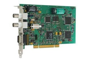
GPS 170 PCI
GPS slot card for PC (PCI/PCI-X Bus).
General description
- PCI Local Bus Interface
- 3.3V or 5V, 33MHz or 66MHz,
- PCI-X compatible
- 2 time trigger inputs
- Pulses per second and per minute
- Periodic interrupts
- RS232 Interface
- IRIG-B/AFNOR time code outputs and 3 programmable TTL outputs
- DCF77-simulation
- Plug and Play
- Antenna connected with up to 300m of standard coaxial cable RG58
- DC-insulated antenna circuit
- Driver software for all popular operating systems
- Flash-EPROM with bootstrap loader
- Including GPS antenna, 20m standard cable and printed manual
Detailed description
The board GPS170PCI has been designed to synchronize the system time of computers with PCI/PCI-X bus interface.
The drivers package for Windows contains a time adjustment service which runs in the background and adjusts the Windows system time continuously and smoothly. A monitor program is also included which lets the user check the status of the device and the time adjustment service, and can be used to modify configurable parameters.
The driver package for Linux contains a kernel driver which allows the board to be used as a reference time source for the NTP daemon which is shipped with most Linux distributions. This also turns the computer into a NTP time server which can also provide accurate time to other NTP clients on the network. Some command line tools can be used to setup configurable parameters and monitor the status of the board.
Additional drivers packages are available for DOS, Novell NetWare, and OS/2. At the bottom of this page there's a link to the download area.
The device's serial port can be used to update the card's firmware. Additionally it can be connected to the serial port of a computer to use the card as reference time source under operating systems where a serial time string is supported, e.g. by NTP, but no kernel device driver is available.
Technical data
| Type of receiver: | 6 channel C/A-code receiver |
|---|---|
| Type of antenna: | Remote powered GPS antenna/converter unit, up to 300m distance to antenna with RG58 and up to 600m distance with RG213 cable |
| Status info: | Fail-LED shows that the internal timing has not been synchronized or that a system error occurred Lock-LED shows that the calculation of the position has been achieved after reset |
| Synchronization time: | Max. 1 minute in normal operation mode, approx. 12 minutes after a cold start (discharged buffer battery) |
| Frequency outputs: | Frequency output 10 MHz, TTL level |
| Pulse outputs: | 3 Programmable TTL outputs, channels 0 and 1 per default configured as Pulse per second (TTL, RS232 level) and pulse per minute (TTL), pulse duration: 200 msec Channel 2 default configuration: DCF77 compatible pulses (TTL level), pulse width: 100/200 msec |
| Accuracy of pulse outputs: | < ± 250ns |
| Interface: | Single serial RS232 interface |
| Data format PC interface: | Binary, byte serial (compatible with Meinberg DCF77 Slot Card PCI511) |
| Data format of interfaces: | Baudrate: 300, 600, 1200, 2400, 4800, 9600, 19200 Baud data format: 7N2, 7E1, 7E2, 8E1, 8N1, 8N2 Time telegram: Meinberg Standard-Telegram, SAT, Uni Erlangen (NTP), SPA, NMEA0183 (RMC) or capture-telegramm |
| Generated time codes: | B002: 100pps, DCLS signal, no carrier, BCD time of year B122: 100pps, AM sinewave signal, 1 kHz carrier, BCD time of year B003: 100pps, DCLS signal, no carrier, BCD time of year, SBS time of day B123: 100pps, AM sinewave signal, 1kHz carrier, BCD time of year, SBS time of day IEEE1344: Code according to IEEE1344-1995, 100pps, AM sinewave signal, 1kHz carrier, BCD time of year, SBS time of day, IEEE1344 expansion for date, timezone, daylight saving and leap second in Control Funktions Segment AFNOR: Code according to NFS-87500, 100pps, AM sinewave signal, 1kHz carrier, BCD time of year, complete date, SBS time of day |
| Unmodulated time code output: | TTL into 50 ohm (active high or active low) |
| Modulated time code output: AM sinewave signal: | 3Vpp (MARK), 1Vpp (SPACE) into 50 ohm |
| Time-Trigger inputs: | Resolution: 100 nsec, triggered by falling TTL slope Time of trigger event readable via computer slot or optional second RS232-interface |
| Electrical connectors: |
BNC female connector for antenna BNC female connector for modulated timecode 9 pin sub D male connector |
| Power supply: | +5V, ca. 400mA +12V, ca. 170mA |
| Backup battery type: | When main power supply fails, hardware clock runs free on quartz basis, almanach data is stored in RAM Life time of lithium battery min. 10 years |
| Board type: | PCI card short |
| Ambient temperature: | 0 ... 50°C / 32 ... 122°F |
| Humidity: | Max. 85% |
| Options: | Additional RS232 interface Fiber optic IRIG B output instead of modulated IRIG B(AM) |

